DIY Breadboard Circuits
Learn the basics of circuitry with a do-it-yourself breadboard circuit kit.
Overview
These ten different circuit builds demonstrate the basics of electricity flow through circuits and familiarize students with circuitry components like photoresistors, push buttons, batteries, LEDs, capacitors, and breadboards. Each build increases in complexity, and all components are reusable so that builds may be disassembled and recreated!
Section Title
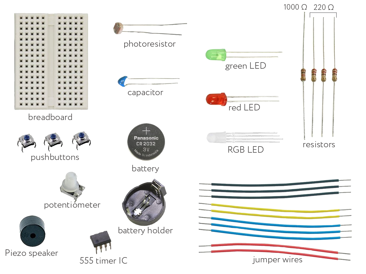
Each kit includes:
Cards
Text
- 1 breadboard
- 1 CR 2032 3V battery
- 1 CR 2032 battery holder
- 1 4.7 µF capacitor
Text
- 10 Jumper wires
- 3 220 Ω resistors (red, red, brown, gold)
- 1 1000 Ω resistor (brown, black, red, gold)
Text
- 1 photoresistor
- 1 Red LED
- 1 Green LED
- 1 RGB LED
Text
- 1 555 Timer IC
- 1 Piezo speaker
- 3 Push buttons
- 1 Potentiometer
WYSIWYG
Before you get started building circuits, familiarize yourself with all of the components.
Section Title
Circuit Builds
Accordion Items
Title
Build 1 - Single LED
Content
- Insert the black jumper wire into the breadboard from A5 to A14.
- Insert the Red jumper wire into the breadboard from J5 to J14.
- Place the Red LED into row 14 with the positive end (longer of the two legs) connecting to the right side, lining up with the red wire and the negative on the left lining up with the black wire.
- Insert the battery into its battery holder and place it in the breadboard connecting negative to black and positive to red.

If the LED does not light up, check for the following:
- Is your LED in backwards?
- Are the jumper wires in the same row as the LED leads?
- Are the jumper wires in the same row as the battery terminals?
Title
Build 2 - Single Push Button
Content
- Insert the black jumper wire into the breadboard from A5 to A16.
- Insert the red jumper wire into the breadboard from J5 to J12.
- Place the red LED into the breadboard with the positive leg (longer of the two legs) inserted into H15 and the negative leg into G17.
- Place the pushbutton horizontally in the middle of the breadboard so the bottom left pin is on row 16 lined up with the black jumper wire and the top right pin is on row 14 lined up with the negative leg of the red LED.
- Insert the battery into its battery holder and place it in the breadboard connecting negative to black and positive to red.
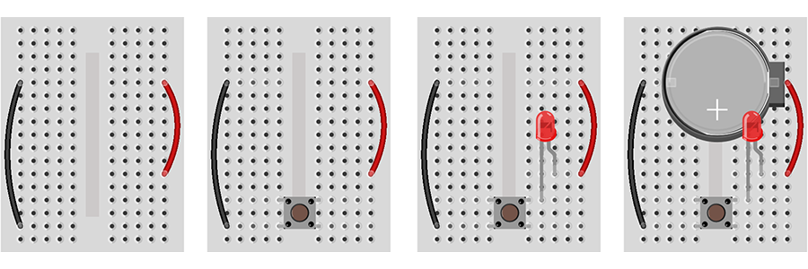
If the LED does not light up, check for the following:
- Is your LED in backwards?
- Are the jumper wires in the same row as the LED leads?
- Are the jumper wires in the same row as the battery terminals?
Title
Build 3 - Photoresistor-Dimmed LED
Content
- Insert the black jumper wire into the breadboard from A5 to A12.
- Insert the Red jumper wire into the breadboard from J5 to J13.
- Place the green LED into the breadboard with the positive leg (longer of the two legs) inserted into F13 and the negative leg into E13.
- Insert the photoresistor into the breadboard from C12 to D13.
- Insert the battery into its battery holder and place it in the breadboard connecting negative to black and positive to red.
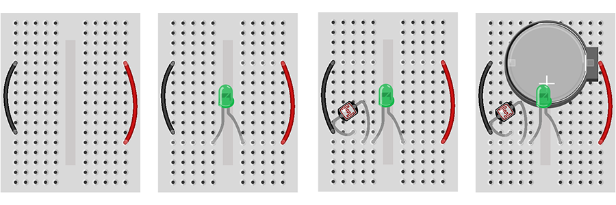
If the LED does not light up, check for the following:
- Is your LED in backwards?
- Are the jumper wires in the same row as the LED leads?
- Are the jumper wires in the same row as the battery terminals?
Title
Build 4 - Double LED Push Button
Content
- Insert the black jumper wire into the breadboard from A5 to A11.
- Insert the red jumper wire into the breadboard from J5 to J11.
- Insert the 220Ω resistor into the breadboard from I11 to I15.
- Place the pushbutton horizontally in the middle of the breadboard so the top pins are on row 15 and opposite sides of the breadboard.
- Place the red LED into the breadboard with the positive leg (longer of the two legs) inserted into C17 and the negative leg into B11.
- Place the green LED into the breadboard with the positive leg inserted into G15 and the negative leg into E11.
- Insert the battery into its battery holder and place it in the breadboard connecting negative to black and positive to red.
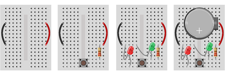
If the LED does not light up, check for the following:
- Is your LED in backwards?
- Are the jumper wires in the same row as the LED leads?
- Are the jumper wires in the same row as the battery terminals?
Title
Build 5 - Photoresistor Blinking LEDs
Content
- Insert the black jumper wire into the breadboard from A3 to A12.
- Insert the red jumper wire into the breadboard from J3 to J12.
- Place the 555 integrated circuit chip into the middle of the breadboard with the top pins on row 12.
- Insert a jumper wire into the breadboard connecting D15 to G12.
- Insert a jumper wire into the breadboard connecting D13 to G14.
- Insert the 1000Ω resistor into the breadboard from C14 to H17.
- Insert the photoresistor into the breadboard from B14 to B15.
- Insert the capacitor into the breadboard from A13 to B12.
- Place the green LED into the breadboard with the positive leg (longer of the two legs) inserted into F17 and the negative leg into C12.
- Place the red LED into the breadboard with the positive leg inserted into I12 and the negative leg into J17.
- Insert the battery into its battery holder and place it in the breadboard connecting negative to black and positive to red.
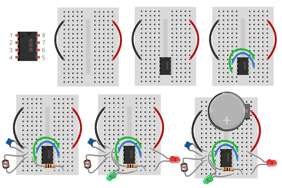
If the LED does not light up, check for the following:
- Is your LED in backwards?
- Are the jumper wires in the same row as the LED leads?
- Are the jumper wires in the same row as the battery terminals?
Title
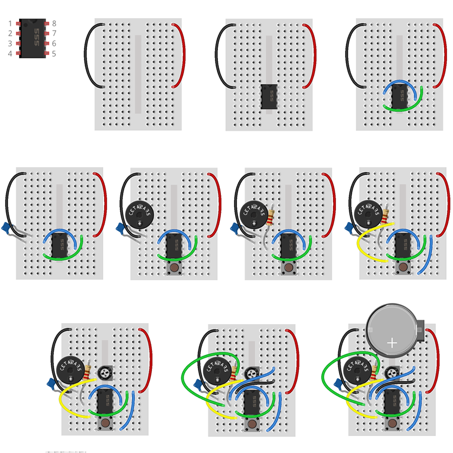
Build 6 - Push Button Buzzer
Content
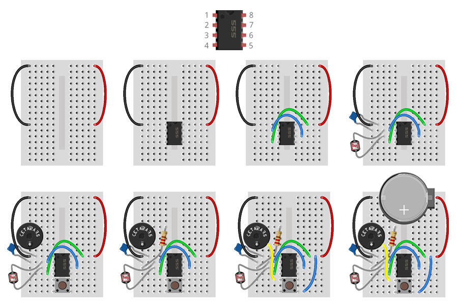
- Insert the black jumper wire into the breadboard from A1 to A11.
- Insert the red jumper wire into the breadboard from J1 to J11.
- Place the 555 integrated circuit chip into the middle of the breadboard with the top pins on row 11.
- Insert a jumper wire into the breadboard connecting D12 to G13.
- Insert a jumper wire into the breadboard connecting D14 to G11.
- Insert the capacitor into the breadboard from A12 to B11.
- Insert the 220Ω resistor into the breadboard from C12 to C13.
- Place the pushbutton horizontally in the middle of the breadboard so the top pins are on row 15 and opposite sides of the breadboard.
- Insert the piezo speaker into the breadboard with the positive pin in A9 and negative to A6.
- Insert the 1000Ω resistor into the breadboard from E6 to A13.
- Insert a jumper wire into the breadboard connecting C9 to D15.
- Insert a jumper wire into the breadboard connecting G17 to I11.
- Insert the battery into its battery holder and place it in the breadboard connecting negative to black and positive to red.
- When you press the push button, the buzzer will sound.
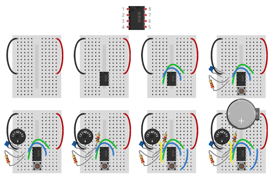
Title
Build 7 - Photoresistor Theremin
Content
- Insert the black jumper wire into the breadboard from A1 to A11.
- Insert the red jumper wire into the breadboard from J1 to J11.
- Place the 555 integrated circuit chip into the middle of the breadboard with the top pins on row 11.
- Insert a jumper wire into the breadboard connecting D12 to G13.
- Insert a jumper wire into the breadboard connecting D14 to G11.
- Insert the capacitor into the breadboard from A12 to B11.
- Insert the photoresistor into the breadboard from C12 to C13.
- Place the pushbutton horizontally in the middle of the breadboard so the top pins are on row 15 and opposite sides of the breadboard.
- Insert the piezo speaker into the breadboard with the positive pin in A9 and negative to A6.
- Insert the 1000Ω resistor into the breadboard from E6 to A13.
- Insert a jumper wire into the breadboard connecting C9 to D15.
- Insert a jumper wire into the breadboard connecting G17 to I11.
- Insert the battery into its battery holder and place it in the breadboard connecting negative to black and positive to red.
- When you press the push button, the buzzer will sound. Covering the photoresistor from light will change the pitch of the buzzer.
Title
Build 8 - Potentiometer-Dimmed LED
Content
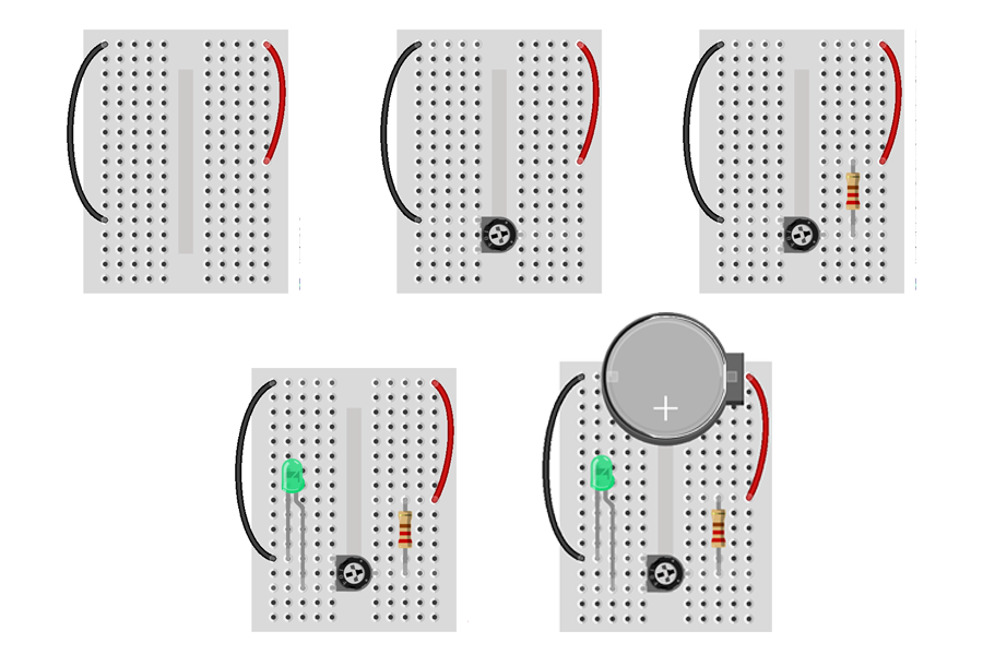
- Insert the black jumper wire into the breadboard from A1 to A13.
- Insert the Red Jumper wire into the breadboard from J1 to J9.
- Place the potentiometer with the two-pin side on the left, top pin in E13 and bottom pin in E15.
- Insert the 220Ω resistor into the breadboard from H9 to H14.
- Place the green LED into the breadboard with the positive leg (longer of the two legs) inserted into C15 and the negative leg in B13.
- Insert the battery into its battery holder and place it in the breadboard connecting the negative to the black and positive to red.
- When you insert the battery, the LED will turn on. Rotating the potentiometer will increase or decrease the brightness of the LED.
If the LED does not light up, check for the following:
- Is your LED in backwards?
- Are the jumper wires in the same row as the LED leads?
- Are the jumper wires in the same row as the battery terminals?
Title
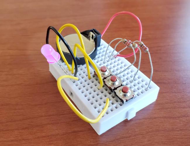
Build 9 - Push Button RGB LED
Content
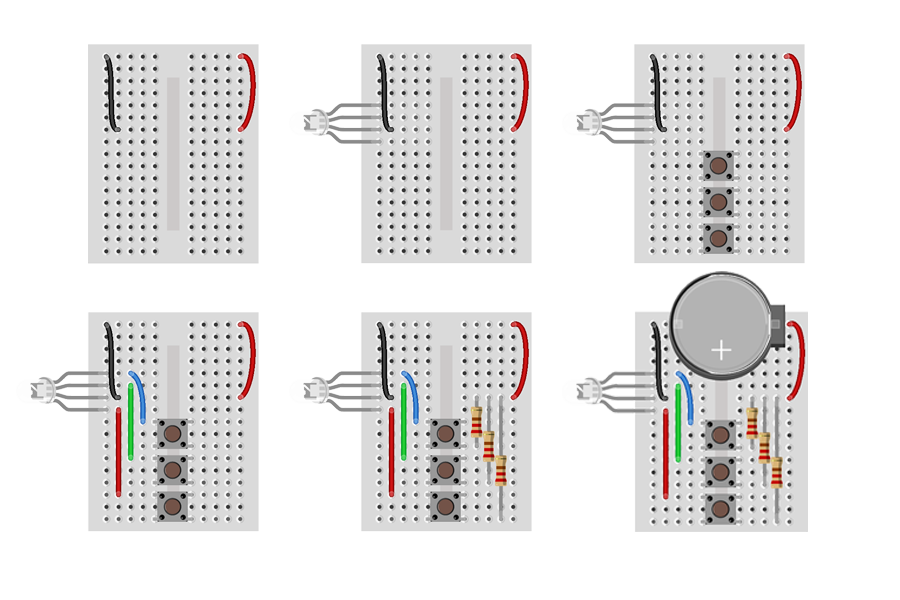
- Insert the black jumper wire into the breadboard from A1 to B7.
- Insert the Red Jumper wire into the breadboard from J1 to J7.
- Insert the RGB LED into the breadboard in A4 to A8. The longest of the four legs is the ground and should be in A7.
- Place the three pushbuttons horizontally in the middle of the breadboard. The three pushbuttons pins should be at: E9-F9-E11-F11, E12-F12-E14-F14, E15-F15-E17-F17
- Insert a jumper wire into the breadboard connecting C5 to D9.
- Insert a jumper wire into the breadboard connecting C6 to C12.
- Insert a jumper wire into the breadboard connecting B8 to B15.
- Insert the 220Ω resistor into the breadboard from G7 to G11.
- Insert the 220Ω resistor into the breadboard from H7 to H14.
- Insert the 220Ω resistor into the breadboard from I7 to I17.
- Insert the battery into its battery holder and place it in the breadboard, connecting negative to black and positive to red.
- Pressing the push buttons will change the color of the RGB LED. Pressing push buttons simultaneously will combine colors.
Title
Build 10 - Potentiometer Controlled Buzzer
Content
- Insert the black jumper wire into the breadboard from A1 to A11.
- Insert the red jumper wire into the breadboard from J1 to J11.
- Place the 555 integrated circuit chip into the middle of the breadboard with the top pins on row 11.
- Insert a jumper wire into the breadboard connecting D12 to G13.
- Insert a jumper wire into the breadboard connecting D14 to G11.
- Insert the capacitor into the breadboard from A12 to B11 and the piezospeaker into A6 to A9 (be sure to place the positive end on the bottom).
- Place the pushbutton horizontally in the middle of the breadboard so the top pins are on in E15 and F15.
- Insert the 220Ω resistor into the breadboard from E6 to A13.
- Insert a jumper wire into the breadboard connecting E9 to D15.
- Insert a jumper wire into the breadboard connecting G17 to I11.
- Place the potentiometer with the two-pin side on the right, top pin in F7 and bottom pin in F9.
- Insert a jumper wire into the breadboard connecting D8 to B13.
- Insert a jumper wire into the breadboard connecting H7 to C12.
- Insert a jumper wire into the breadboard connecting H9 to D11.
- Insert the battery into its battery holder and place it in the breadboard, connecting negative to black and positive to red.
- Pressing the push button will cause the buzzer to sound. Rotating the potentiometer will alter the pitch of the buzzer.
